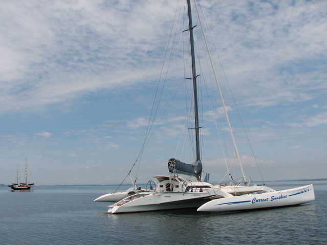
As you know from changing your car battery – they are heavy, real heavy. And for a light ex-racing trimaran like Current Sunshine this makes for a real challenge because it can’t carry much weight.

Most cruising yachts are keel boats, and use ballast for stability – so in some ways extra weight can help with such a boat’s stability. On the other hand, Current Sunshine uses its great width (36 feet) for stability. And because it was built as a short-handed racing boat it was never designed to carry any cargo, and so I have to be really careful not to overload her with batteries.
When it was refitted for cruising some extra weight was added for the new cabin arrangements, so she’s already heavier than designed. As part of the refit she was lengthened by a little over a metre in the stern, so that gives her a little more load carrying capacity. This was needed to carry the 25HP outboard motor and its fuel.
My objective with the new electric motor and batteries was to keep to same the weight as outboard engine and fuel. A 25HP Yamaha outboard weighs about 80kg, and its normal fuel load is a 25 litre main tank and two 20 litre jerry cans. This gives me a total of about 140kg to work with.

The electric drive is an Torqeedo Cruise 4 weighing in about 18kg and that leaves me 122kg for batteries.
To begin with I explored the possibility of Lithium batteries, seeking lightness, but the price of $60,000 was ridiculously expensive, and so I abandoned that idea for a while.
And then I discovered ThunderSky lithium batteries. The price for the a suitable battery pack was around $10,000 – amazing reduction from the $60,000 quoted by a French company. ThunderSky batteries are from China and I bought them through the Australian distributor, EV Power.
They weigh in at 118kg for a 16 cell battery pack and so they match my weight limits nicely.

Each cell has 200Ah of capacity at 3.2 volts, giving a pack voltage of 51.2. These lithium batteries are known as LFP cells which are more thermally stable than earlier varieties, and don’t pose the same fire risk that dogged the early technology.
They have some substantial advantages over lead-acid batteries – much more than I had first realised…
The weight advantage is significant when simply comparing amphour capacity against mass. On this simple level, to provide the same nominal amphour capacity using lead-acid batteries of the AGM type would require 8 batteries each of 6 volts and 200 ah. These are around 30 kg each. For example an Absorbed Power battery, of about the right size is 33.6 kg. This battery is listed on their website as a 225 ah battery. And eight of these would weigh in at 269kg – over a quarter of a tonne. But when you compare it carefully to the LFP batteries they don’t even come close. There’s more to it than meets the eye…
Lets look at the real capacity of these AGM batteries when under the full load of the 4kw Torqeedo motor. This converts to a current of around 80 amps when the batteries are at 50 volts. The Absorbed Power data sheet shows that for a current of 37.5 amps the capacity is no longer 225 ah, but 187.5 ah. And for a current of 132 amps its capacity is 132 amphours. Somewhere between these two points is the capacity when discharging at 80 amps – I estimate it to be around 160 ah. So we’ll really need more than 8 batteries to get the equivalent capacity of the LFPs. But before we figure this out there’s more to consider.
On the other hand, the nice thing about the LFP batteries is that at high loads, their capacity is practically unchanged – and they can easily handle loads way more than 80 amps – in fact up to 3C (that is, 3 x capacity) or 600 amps. So we’re nowhere near those levels.
A critical factor is depth of dicharge, or DOD. The Absorbed Power batteries are listed as having a life of 750 cycles at 50% DOD. The LFP batteries are listed as having a life of 2000 cycles at a DOD of 80%. So lets work on these figures to begin with…
For the AGMs, I don’t want to go below 50% DOD in regular use, so the regular usable capacity is half of the rated capacity – which at the load I have, is half of 160ah, or 80 ah. For the LFP batteries, at 80% DOD, the regular usable capacity is 80% of 200ah, which is 160ah. Interesting huh – the AGMs real capacity is half of the LFPs. So it looks like we’d need double the capacity… but there’s more to consider yet. (and even that would be over half a tonne of batteries – whew!)
Something else I notice about the LFPs is that the voltage doesn’t sag under load – well, not much anyway. But the AGMs do – and even more as the battery is discharged. I don’t have the figures for this. But what it means is that as the voltage drops, to get the same power, that is watts, more current is needed, which reduces capacity even more.
And what about price? At $10,000 it seems these LFPs are expensive huh. But if I bought them today the cost would be around $7000, so already they’ve dropped. The price of a 6v 200 ah AGM is around $350 and we need at least 16 of them to get close to the capacity of the LFPs, which comes to $5600.00 So even with AGMs the first cost is significant and only 20% cheaper. But when we consider that in the lifetime of the LFPs (2000 cycles) I’d have to buy two other sets of AGMs, (750 cycles) the truth is that the LFPs are far less expensive than AGMs.
But wait, there’s more…
Another important aspect for a solar boat is the charging conditions. First there’s the charge recovery or the ability to get the electrons back into the battery for more use. The LFPs have the nice property of virtually no losses when charging. That is, if I put 100 amphours into the battery, that means I have 100 amphours available for use from the battery.
But the AGMs have about a 90% charge efficiency factor. That is, to get 100 amphours of usable power in the battery, I have to put back about 110 amphours. So to achieve the same usable power I’d need a 10% increase in my solar panels if I choose AGM batteries. And this would increase the cost of an AGM system and this will brings its first cost even closer to the cost of the LFPs.

And secondly, and perhaps more important, is the low rate of charge recovery on a solar boat. Because the power comes from the sun or wind at a fairly slow rate, it may take a week or two to recover the power used from a burst of motor use. With LFP batteries it doesn’t matter if they sit at a low state of charge. But for AGMs it can be damaging if they are left at 50% state of charge for any length of time. Do you leave the batteries in this low state? Run the genset? Have an even bigger pack, say double again, so that the discharge is only 25%. Its becoming ridiculous – doubling the pack again would mean the cost is now more than LFPs and the mass is over one tonne. Or the other alternative of running a genset every time the charge drops erodes the advantages of a solar boat. Or leaving the batteries to recover slowly reduces their life even more from the assumed 750 cycles.
The bottom line is, that on every consideration so far, weight, price, power available, charge retention and longevity, the LFPs are the best choice.
The only disadvantage I’ve found is learning to manage them. They’re different to lead-acids and they need different management. I’m confident that I’ll soon have them set up in a way that requires no more from me than is needed for my lead-acid house batteries. In fact I’m already planning to change my house pack to LFPs as well. But, hey, that’s another story.
To see how this is actually working in practise see the chart tracking motor use and battery status here.

Oh, another thing to keep in mind… she is after all, a sail boat, and the electric motor is an auxiliary propulsion system. The new sails are much lighter than the old dacron and cruise-lam sails. Not sure how much much, but I probably saved around 30kg. Being lighter the new sails are really good in light air. In sailing from Sydney Harbour to Pittwater in winds of around 5 knots we came out of the heads with two monohulls, both of which were running their engines.
We stayed in touch with them just about all the way to Pittwater, and even came close to overtaking one when the wind freshened to around 8 knots. (We think he cranked up the diesel a little). We lost contact only when the wind became a 2 to 3 knot zephyr. So she suffers no real penalty even in the lightest conditions.
Q; What did you use for a charge controller for you solar system?
If I do not exceed 3.6volt per cell (the 95% range on the Thundersky) can I use a “NCHC-24-60 24V Systems, 60A Max. Charge Current”
Made by Flexpower http://www.flexcharge.com
Hi Josh,
Interesting question. The flexcharge charge looks adaptable to LFPs but you need be aware of the quicksand when using such a charger without a battery management system. (BMS)
I’m using a dc-dc converter that takes 12v power from my house batteries when they’re full, and charges the engine batteries at a low rate of between 1 and 3 amps. The actual rate varies depending on the relative voltages of the engine and house packs. I also use a BMS system from EVWorks, and it keeps the individual cells from going over-voltage. I can tell you more about how this works another time if you’d more info, but to be going on with lets talk about the flexcharge.
The disconnect voltage is adjustable and is set at the factory at 2.375v per cell (thats lead-acid cell) which for a 24 volt battery is 12×2.375 = 28.5v.
The reconnect voltage level is 27.4v.
For LFP cells, with 8 cells for a 24v bank, a cutoff level of 3.6 volts per cell converts to 28.8 volts for the pack, so the controller will need to adjusted slightly for this exact voltage. If left alone at the factory setting the cut-off voltage will be 3.563v per cell. Which you may consider close enough to the target of 3.6v per cell.
The reconnect voltage of 27.4v for the bank equates to 3.425v per cell.
Will you be using a BMS? The BMS from EV Works includes “cell protectors” which monitor the voltage on each cell and take action if the voltage exceeds 3.84v on any cell, or drops to 2.5v on any cell. This can protect the individual cells from over or under voltage, within limits.
Consider what can happen without cell protection…
Say the cells are not at equal voltage (which is probably the case when they arrive from the factory, half charged) and one of them is higher than the rest. for the purpose of example, what happens if 7 of the cells are at more or less equal voltage, and one cell is at a higher voltage? 7 cells at 3.4 volts (7 x 3.4 = 23.8v ) and the one higher cell is at 4.6volts. The total voltage of the pack is 28.4, which is still below the cutoff level of the flexcharge charger. So the charger will still be putting in maximum amps to the pack at this point. But the one cell at 4.6 volts is already over its maximum voltage of 4.2, and the charger knows nothing about this and so keeps merrily on its way until it gets to 28.5 volts. At this cutoff point the cell may already be destroyed.
Having said that it seems that you can get by without a BMS as long as manually balance all the cells. And if you plan to do it manually I’d recommend you read Jack Rickard’s blog where he talks about manual balancing and also makes a strong case for bottom balancing.
From what I’ve seen on my pack, when the voltage is high, around 60 volts, which is just before the cell protectors start working, there is a natural decay of voltage back to around 56 volts when the charging source is removed. I guess that this decay would also work to keep cells balanced after you had done an initial manual balance, and maybe is why Jack Rickard has seen it work.
Anyway, back to the flexcharge charger… the voltage settings look ok to me as it comes out of the box, if you plan to manually balance, but if you are using a BMS such as from EVWorks, you’d likely want to match the 3.84v cutoff level off level of the cell protectors so they get to do their work of balancing. And you’d need to use the relay of the BMS to cutoff the charging if/when any cell exceeds the limit.
The nice thing about the flexcharge NCHC is that it has a load diversion option which is good for wind generators and towing generators (to keep them loaded) as well as giving you the chance to have ‘free’ hot water. Free in the sense that otherwise this power would be wasted.
–Chris
Hi Chris, I have a set of LIPO4 thunderskys x8 @3.2 v on their way to my boat (Fusion 40) , (Had them a while ) and now getting closer to set up .
I have read your comments regards the Flex charger , could you advise/ recommend any other programmable chargers that could work as well .
I intend to cruise with several forms of charging , solar, wind and 2×80 watt
alternators on my 30 Yanmars and must admit after long reading sessions of research Chargers etc I am still pretty confused with all the tech stuff , but I do have the EV management system and understood your logic re the financial gains over the old Lead Acid .
There are not many (none I have found) installers who know anything about this latest technology so any info would be appreciated .
Lance
Hi Lance,
I have a Xantrex load diversion charger – called C-Series controllers. (And now using this on AGM house battery) These allow you to set the voltage for bulk and float charging. Morninstar also have some charge controllers that are flexible – they have a RS232 interface that allows you to use your computer to change the charge setpoints. I haven’t used one of these but I’m confident it would allow you to set it to a suitable voltage.
Regarding the bulk and float settings… the LFP batteries don’t need float part of the cycle. And the way the bulk/absorbtion part works is exactly right for LFP batteries – that is, it charges at maximum current until the voltage rises to the bulk setting, then it gradually reduces current keeping the fixed voltage.
I’ll be changing my setup soon to have LFP house batteries as well, and will need to set up my charge control differently to allow for this. I’m not quite sure how to handle the float setting. What I’m thinking to do is to set the float charge to a suitably low level, say just matching the resting voltage of the cells, so that after they are fully charged by the bulk cycle, the float cycle pretty much doesn’t do anything. For 12v house pack I have in mind to set the values at 15 volts for bulk charging and 13.5 volts for float.
there needs to be protection against the possibility of one cell being high, and the pack voltage not being high enough to trigger shutoff of the charger. This might happen when the cells are unbalanced in the early stages. In this case the BMS will have sensed the high voltage and have triggered the charging relay to open.
This is ok for mains power charger, which is typically used by Electric Vehicles. But what part of the solar charging circuit would the relay be opening?
In the case of solar panels only, and using a standard solar charger, the supply wires circuit from the panels could be opened – but then the solar panels are open circuit which I think is not so good. So really I’m not sure what’s best here.
In the case of load diversion type controller, and which could also have other generating sources such as wind and water turbines, the incoming power could be diverted direct to the diversion load. This is how it is on Current Sunshine, and the diversion load is a water heater. But to do this diversion requires closing of a circuit, not opening, as the charging relay does.
What I plan to do is to have a relay which has two contacts, one of which is normally open, and one which is normally closed. (maybe I’ll use a double-throw contactor).
When the charging is ok, that is no cells are over voltage, the power would be going to the charge controller and it manages how much power goes to the batteries. This power would go through the normally closed contact – from the charging sources to the charge controller.
When the charging is not ok, that is, one or more cells have gone overvoltage, the relay on the BMS opens. This allows the contactor to open, but in doing so, its other set of contacts, which are normally open, are now closed and the power from the source can go directly to load diversion, and nothing gets to the batteries.
After a few cycles the batteries will become balanced, and this type of shutdown should not happen any more. From now on the pack voltage will guide the charge controller properly in reducing the charge to the proper level.
Here is a diagram from the Xantrex manual, and you can see its straightforward to set the voltage.